VS-HOT200C080
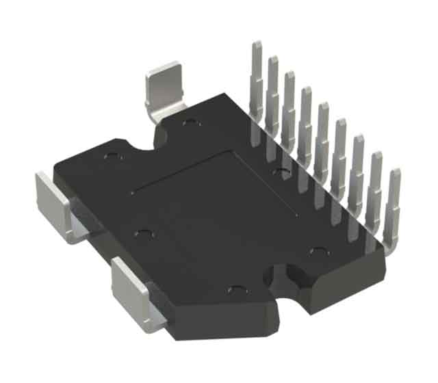
www.vishay.com Vishay Semiconductors FlatPAK HC0 Transfer Mold Power Module
Half Bridge -Power MOSFET, 200 A
FEATURES
• Half bridge inverter
• Current sensing and temperature sensing
• Electrically isolated exposed DBC substrate
• C snubber for low EMI
• Qualified according to AQG324 guidelines
• PPAP capable
• Epoxy compound UL 94 V-0 certified
• Material categorization: for definitions of compliance
please see www.vishay.com/doc?99912 PRIMARY CHARACTERISTICS
VDSS 80 V RDS(on), Q1 (chip level) 0.45 mΩ ID 195 A at 80 °C Type Modules -MOSFET Package FlatPAK HC0 ABSOLUTE MAXIMUM RATINGS (TC = 25 °C unless otherwise specified)
PARAMETER SYMBOL TEST CONDITIONS MAX. UNITS 80 V MOSFET
Drain to source voltage VDSS
TC = 25 °C Continuous drain current, VGS at 10 V ID 243 TC = 80 °C 195 TC = 118 °C 150 Pulsed drain current IDM TC = 25 °C, tp = 250 μs, square waveform 1050
1530 Pulsed source current (body diode) ISM TC = 150 °C, tp = 1 ms, square waveform Power dissipation PD TC = 25 °C Gate to source voltage VGS Single pulse avalanche energy EAS Single pulse avalanche current IAS A 194 W ± 20 V TC = 25 °C, L = 1 mH, VGS = 10 V 1800 mJ TC = 25 °C, L = 1 mH, VGS = 10 V 60 A 2000 V MODULE
Insulation voltage (RMS) VISOL Any terminal to case, t = 1 s THERMAL-MECHANICAL SPECIFICATIONS
PARAMETER MIN. TYP. MAX. UNITS Junction temperature range SYMBOL
TJ -55 -175 °C Storage temperature range TStg -40 -150 °C Operating temperature range Top -40 -150 °C -0.77 Flat, greased surface (1) -0.15 -10 -nH Maximum load, test speed: 0.5 mm/min (2) 3 -22 kN -10 -g -0.7 -Nm Junction to case MOSFET RthJC Case to heat sink Module RthCS Package parasitic stray inductance
Compression force TEST CONDITIONS Lp Weight
Mounting torque Mounting screw -M3 Case style °C/W FlatPAK HC0 Notes …