Datasheet Texas Instruments TPS40211 — Datenblatt
| Hersteller | Texas Instruments |
| Serie | TPS40211 |
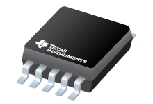
4,5-V bis 52-V Eingangsstrom-Boost-Regler
Datenblätter
Datasheet TPS40210, TPS40211
PDF, 1.8 Mb, Revision: F, Datei veröffentlicht: Dec 17, 2014, Seiten: 52
TPS4021x 4.5-V to 52-V Input Current Mode Boost Controller
TPS4021x 4.5-V to 52-V Input Current Mode Boost Controller
Auszug aus dem Dokument
Status
| TPS40211DGQ | TPS40211DGQG4 | TPS40211DGQR | TPS40211DGQRG4 | TPS40211DRCR | TPS40211DRCRG4 | TPS40211DRCT | |
|---|---|---|---|---|---|---|---|
| Lifecycle Status | Active (Recommended for new designs) | Active (Recommended for new designs) | Active (Recommended for new designs) | Active (Recommended for new designs) | Active (Recommended for new designs) | Active (Recommended for new designs) | Active (Recommended for new designs) |
| Manufacture's Sample Availability | Yes | Yes | No | No | No | No | Yes |
Verpackung
| TPS40211DGQ | TPS40211DGQG4 | TPS40211DGQR | TPS40211DGQRG4 | TPS40211DRCR | TPS40211DRCRG4 | TPS40211DRCT | |
|---|---|---|---|---|---|---|---|
| N | 1 | 2 | 3 | 4 | 5 | 6 | 7 |
| Pin | 10 | 10 | 10 | 10 | 10 | 10 | 10 |
| Package Type | DGQ | DGQ | DGQ | DGQ | DRC | DRC | DRC |
| Industry STD Term | HVSSOP | HVSSOP | HVSSOP | HVSSOP | VSON | VSON | VSON |
| JEDEC Code | S-PDSO-G | S-PDSO-G | S-PDSO-G | S-PDSO-G | S-PDSO-N | S-PDSO-N | S-PDSO-N |
| Package QTY | 80 | 80 | 2500 | 2500 | 3000 | 3000 | 250 |
| Carrier | TUBE | TUBE | LARGE T&R | LARGE T&R | LARGE T&R | LARGE T&R | SMALL T&R |
| Device Marking | 40211 | 40211 | 40211 | 40211 | 4211 | 4211 | 4211 |
| Width (mm) | 3 | 3 | 3 | 3 | 3 | 3 | 3 |
| Length (mm) | 3 | 3 | 3 | 3 | 3 | 3 | 3 |
| Thickness (mm) | 1.02 | 1.02 | 1.02 | 1.02 | .9 | .9 | .9 |
| Pitch (mm) | .5 | .5 | .5 | .5 | .5 | .5 | .5 |
| Max Height (mm) | 1.1 | 1.1 | 1.1 | 1.1 | 1 | 1 | 1 |
| Mechanical Data | Herunterladen | Herunterladen | Herunterladen | Herunterladen | Herunterladen | Herunterladen | Herunterladen |
Parameter
| Parameters / Models | TPS40211DGQ | TPS40211DGQG4 | TPS40211DGQR | TPS40211DGQRG4 | TPS40211DRCR | TPS40211DRCRG4 | TPS40211DRCT |
|---|---|---|---|---|---|---|---|
| Dimming Method | Analog,PWM | Analog,PWM | Analog,PWM | Analog,PWM | Analog,PWM | Analog,PWM | Analog,PWM |
| Input Voltage, Type | DC/DC | DC/DC | DC/DC | DC/DC | DC/DC | DC/DC | DC/DC |
| Iout(Max), A | 5 | 5 | 5 | 5 | 5 | 5 | 5 |
| Iq(Typ), mA | 1.5 | 1.5 | 1.5 | 1.5 | 1.5 | 1.5 | 1.5 |
| Operating Temperature Range, C | -40 to 125 | -40 to 125 | -40 to 125 | -40 to 125 | -40 to 125 | -40 to 125 | -40 to 125 |
| Package Group | MSOP-PowerPAD | MSOP-PowerPAD | MSOP-PowerPAD | MSOP-PowerPAD | VSON | VSON | VSON |
| Package Size: mm2:W x L, PKG | 10MSOP-PowerPAD: 15 mm2: 4.9 x 3(MSOP-PowerPAD) | 10MSOP-PowerPAD: 15 mm2: 4.9 x 3(MSOP-PowerPAD) | 10MSOP-PowerPAD: 15 mm2: 4.9 x 3(MSOP-PowerPAD) | 10MSOP-PowerPAD: 15 mm2: 4.9 x 3(MSOP-PowerPAD) | 10VSON: 9 mm2: 3 x 3(VSON) | 10VSON: 9 mm2: 3 x 3(VSON) | 10VSON: 9 mm2: 3 x 3(VSON) |
| Power Factor Correction, Min | N/A | N/A | N/A | N/A | N/A | N/A | N/A |
| Rating | Catalog | Catalog | Catalog | Catalog | Catalog | Catalog | Catalog |
| Regulated Outputs | 1 | 1 | 1 | 1 | 1 | 1 | 1 |
| Special Features | Adjustable Switch Frequency,Enable/Shutdown,Soft Start,Synchronization Pin | Adjustable Switch Frequency,Enable/Shutdown,Soft Start,Synchronization Pin | Adjustable Switch Frequency,Enable/Shutdown,Soft Start,Synchronization Pin | Adjustable Switch Frequency,Enable/Shutdown,Soft Start,Synchronization Pin | Adjustable Switch Frequency,Enable/Shutdown,Soft Start,Synchronization Pin | Adjustable Switch Frequency,Enable/Shutdown,Soft Start,Synchronization Pin | Adjustable Switch Frequency,Enable/Shutdown,Soft Start,Synchronization Pin |
| Switching Frequency(Max), kHz | 1000 | 1000 | 1000 | 1000 | 1000 | 1000 | 1000 |
| Switching Frequency(Min), kHz | 35 | 35 | 35 | 35 | 35 | 35 | 35 |
| Topology | Boost | Boost | Boost | Boost | Boost | Boost | Boost |
| Type | Inductive | Inductive | Inductive | Inductive | Inductive | Inductive | Inductive |
| Vin(Max), V | 52 | 52 | 52 | 52 | 52 | 52 | 52 |
| Vin(Min), V | 4.5 | 4.5 | 4.5 | 4.5 | 4.5 | 4.5 | 4.5 |
| Vout(Max), V | 52 | 52 | 52 | 52 | 52 | 52 | 52 |
| Vout(Min), V | 7 | 7 | 7 | 7 | 7 | 7 | 7 |
| Vref, V | 0.26 | 0.26 | 0.26 | 0.26 | 0.26 | 0.26 | 0.26 |
Öko-Plan
| TPS40211DGQ | TPS40211DGQG4 | TPS40211DGQR | TPS40211DGQRG4 | TPS40211DRCR | TPS40211DRCRG4 | TPS40211DRCT | |
|---|---|---|---|---|---|---|---|
| RoHS | Compliant | Compliant | Compliant | Compliant | Compliant | Compliant | Compliant |
Anwendungshinweise
- TPS40211 - SEPIC Design for MR-16 LEDPDF, 2.6 Mb, Datei veröffentlicht: Oct 27, 2010
This document describes a reference design for multifaceted reflector MR-16 LED lighting by using the TPS40211 to construct a SEPIC converter. This driver provides 700 mA to a string of three white LEDs and has the capability to operate with 12 Vac or 12 Vdc. The TPS40211 has been selected for SEPIC application because it offers many advantages – long lifetime as the discard of E-cap in the design - New current-mode PWM controllers support boost, flyback, SEPIC and LED-driverPDF, 314 Kb, Datei veröffentlicht: Aug 6, 2008
- Q3 2008 Issue Analog Applications JournalPDF, 1.2 Mb, Datei veröffentlicht: Aug 6, 2008
- Practical Feedback Loop Analysis for Current-Mode Boost ConverterPDF, 557 Kb, Datei veröffentlicht: Mar 7, 2014
- Basic Calculation of a Boost Converter's Power Stage (Rev. C)PDF, 186 Kb, Revision: C, Datei veröffentlicht: Jan 8, 2014
This application note gives the equations to calculate the power stage of a boost converter built with an IC with integrated switch and operating in continuous conduction mode. It is not intended to give details on the functionality of a boost converter (see Reference 1) or how to compensate a converter. See the references at the end of this document if more detail is needed.
Modellreihe
Serie: TPS40211 (7)
Herstellerklassifikation
- Semiconductors > Power Management > LED Driver > Illumination & General Lighting LED Driver