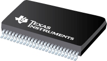
Datasheet Texas Instruments SN74LVCH16240A — Datenblatt
| Hersteller | Texas Instruments |
| Serie | SN74LVCH16240A |

16-Bit-Puffer / Treiber mit 3-Zustands-Ausgängen
Datenblätter
16-Bit Buffer/Driver With 3-State Outputs datasheet
PDF, 314 Kb, Revision: H, Datei veröffentlicht: Aug 13, 2002
Auszug aus dem Dokument
Preise
Status
| SN74LVCH16240ADGGR | SN74LVCH16240ADL | SN74LVCH16240ADLR | |
|---|---|---|---|
| Lifecycle Status | Active (Recommended for new designs) | Active (Recommended for new designs) | Active (Recommended for new designs) |
| Manufacture's Sample Availability | No | No | No |
Verpackung
| SN74LVCH16240ADGGR | SN74LVCH16240ADL | SN74LVCH16240ADLR | |
|---|---|---|---|
| N | 1 | 2 | 3 |
| Pin | 48 | 48 | 48 |
| Package Type | DGG | DL | DL |
| Industry STD Term | TSSOP | SSOP | SSOP |
| JEDEC Code | R-PDSO-G | R-PDSO-G | R-PDSO-G |
| Package QTY | 2000 | 25 | 1000 |
| Carrier | LARGE T&R | TUBE | LARGE T&R |
| Device Marking | LVCH16240A | LVCH16240A | LVCH16240A |
| Width (mm) | 6.1 | 7.49 | 7.49 |
| Length (mm) | 12.5 | 15.88 | 15.88 |
| Thickness (mm) | 1.15 | 2.59 | 2.59 |
| Pitch (mm) | .5 | .635 | .635 |
| Max Height (mm) | 1.2 | 2.79 | 2.79 |
| Mechanical Data | Herunterladen | Herunterladen | Herunterladen |
Parameter
| Parameters / Models | SN74LVCH16240ADGGR | SN74LVCH16240ADL | SN74LVCH16240ADLR |
|---|---|---|---|
| Bits | 16 | 16 | 16 |
| F @ Nom Voltage(Max), Mhz | 100 | 100 | 100 |
| ICC @ Nom Voltage(Max), mA | 0.02 | 0.02 | 0.02 |
| Operating Temperature Range, C | -40 to 85 | -40 to 85 | -40 to 85 |
| Output Drive (IOL/IOH)(Max), mA | -24/24 | -24/24 | -24/24 |
| Package Group | TSSOP | SSOP | SSOP |
| Package Size: mm2:W x L, PKG | 48TSSOP: 101 mm2: 8.1 x 12.5(TSSOP) | 48SSOP: 164 mm2: 10.35 x 15.88(SSOP) | 48SSOP: 164 mm2: 10.35 x 15.88(SSOP) |
| Rating | Catalog | Catalog | Catalog |
| Schmitt Trigger | No | No | No |
| Technology Family | LVC | LVC | LVC |
| VCC(Max), V | 3.6 | 3.6 | 3.6 |
| VCC(Min), V | 2 | 2 | 2 |
| Voltage(Nom), V | 1.8,2.5,2.7,3.3 | 1.8,2.5,2.7,3.3 | 1.8,2.5,2.7,3.3 |
| tpd @ Nom Voltage(Max), ns | 5,4.2 | 5,4.2 | 5,4.2 |
Öko-Plan
| SN74LVCH16240ADGGR | SN74LVCH16240ADL | SN74LVCH16240ADLR | |
|---|---|---|---|
| RoHS | Compliant | Compliant | Compliant |
Anwendungshinweise
- Bus-Hold CircuitPDF, 418 Kb, Datei veröffentlicht: Feb 5, 2001
When designing systems that include CMOS devices, designers must pay special attention to the operating condition in which all of the bus drivers are in an inactive, high-impedance condition (3-state). Unless special measures are taken, this condition can lead to undefined levels and, thus, to a significant increase in the device?s power dissipation. In extreme cases, this leads to oscillation of
Modellreihe
Serie: SN74LVCH16240A (3)
Herstellerklassifikation
- Semiconductors> Logic> Buffer/Driver/Transceiver> Inverting Buffer/Driver