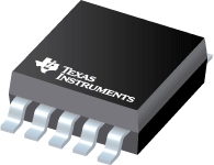
Datasheet Texas Instruments TPS62052DGSR — Datenblatt
| Hersteller | Texas Instruments |
| Serie | TPS62052 |
| Artikelnummer | TPS62052DGSR |

1,5-V-Ausgang, 800 mA, 10 V Vin, 95% effizienter Abwärtswandler in MSOP-10 10-VSSOP -40 bis 85
Datenblätter
TPS6205x 800-mA Synchronous Step-Down Converter datasheet
PDF, 1.1 Mb, Revision: F, Datei veröffentlicht: Jun 26, 2015
Auszug aus dem Dokument
Status
| Lifecycle Status | Active (Recommended for new designs) |
| Manufacture's Sample Availability | No |
Verpackung
| Pin | 10 |
| Package Type | DGS |
| Industry STD Term | VSSOP |
| JEDEC Code | S-PDSO-G |
| Package QTY | 2500 |
| Carrier | LARGE T&R |
| Device Marking | BGC |
| Width (mm) | 3 |
| Length (mm) | 3 |
| Thickness (mm) | 1.02 |
| Pitch (mm) | .5 |
| Max Height (mm) | 1.07 |
| Mechanical Data | Herunterladen |
Parameter
| Control Mode | Voltage Mode |
| Duty Cycle(Max) | 100 % |
| Iout(Max) | 0.8 A |
| Iq(Typ) | 0.012 mA |
| Operating Temperature Range | -40 to 85 C |
| Package Group | VSSOP |
| Rating | Catalog |
| Regulated Outputs | 1 |
| Special Features | Enable,Frequency Synchronization,Light Load Efficiency,Power Good,Synchronous Rectification |
| Switching Frequency(Max) | 1000 kHz |
| Switching Frequency(Min) | 600 kHz |
| Type | Converter |
| Vin(Max) | 10 V |
| Vin(Min) | 2.7 V |
| Vout(Max) | 1.5 V |
| Vout(Min) | 1.5 V |
Öko-Plan
| RoHS | Compliant |
Design Kits und Evaluierungsmodule
- Evaluation Modules & Boards: TPS62052EVM-234
TPS62052 Evaluation Module
Lifecycle Status: Active (Recommended for new designs) - Evaluation Modules & Boards: TPS62050EVM-234
TPS62050 Evaluation Module
Lifecycle Status: Active (Recommended for new designs)
Anwendungshinweise
- Adding Hysteresis to Low Battery Input on the TPS6205x (Rev. A)PDF, 89 Kb, Revision: A, Datei veröffentlicht: Nov 28, 2007
The low-battery input (LBI), available on several step-down converters, is often used to shut down the converter when the input voltage falls below a set threshold. This prevents damage to the battery and signals that the battery is at the end of its life and should be charged or replaced. Batteries have internal resistance that causes the voltage to drop as the load increases. This internal resis - Optimizing Resistor Dividers at a Comparator (Rev. A)PDF, 120 Kb, Revision: A, Datei veröffentlicht: Jun 3, 2013
- Five steps to a great PCB layout for a step-down converterPDF, 162 Kb, Datei veröffentlicht: Jan 29, 2015
- Understanding the Absolute Maximum Ratings of the SW Node (Rev. A)PDF, 755 Kb, Revision: A, Datei veröffentlicht: Jan 13, 2012
- Testing tips for applying external power to supply outputs without an input voltPDF, 110 Kb, Datei veröffentlicht: Oct 24, 2016
- Basic Calculation of a Buck Converter's Power Stage (Rev. B)PDF, 202 Kb, Revision: B, Datei veröffentlicht: Aug 17, 2015
- Extending the Soft Start Time Without a Soft Start Pin (Rev. B)PDF, 387 Kb, Revision: B, Datei veröffentlicht: Jun 15, 2017
- Choosing an Appropriate Pull-up/Pull-down Resistor for Open Drain OutputsPDF, 130 Kb, Datei veröffentlicht: Sep 19, 2011
- IQ: What it is what it isn’t and how to use itPDF, 198 Kb, Datei veröffentlicht: Jun 17, 2011
- Performing Accurate PFM Mode Efficiency Measurements (Rev. A)PDF, 418 Kb, Revision: A, Datei veröffentlicht: Dec 11, 2018
When performing measurements on DC-DC converters using pulse frequency modulation(PFM)or any power save mode proper care must be taken to ensure that the measurements are accurate. An accurate PFM mode efficiency measurement is critical for systems which require high efficiency at low loads such as in smart home systems tablets wearables and metering.
Modellreihe
Serie: TPS62052 (3)
- TPS62052DGS TPS62052DGSG4 TPS62052DGSR
Herstellerklassifikation
- Semiconductors > Power Management > Non-isolated DC/DC Switching Regulator > Step-Down (Buck) > Buck Converter (Integrated Switch)